A $10 Megasquirt "Dashboard"
Now that I have both my cars tuned pretty well with their Megasquirts,
there's no longer a need to carry a laptop around while I'm driving.
That's a good thing, but I would still like to have some feedback from
the MS. Things like Coolant temp, battery voltage and AFR are being
sampled frequently and I'd like to see that the readings behave well.
For about $2 on eBay you can get a 16x2 character backlit LCD display.
Two lines with 16 characters on each gives scope for quite a lot of
information. Hook one of these up to a microcontroller talking
RS-232 to the Megasquirt and you have the makings of a small digital
dashboard. Anything against the idea?
I bought a few of them to experiment with. Their biggest drawback
is that their refresh speed is slow. The internal protocol runs pretty
fast, but the physical characters on the LCD kind of "fade" gradually
from the old character to the new. If you try to update it too
frequently (and even twice per second is too frequent) you end up with
an unreadable blob.
I'm sure it's possible to find faster refreshing LCDs but, for a
numeric dashboard instrument, I don't think it is a killer problem.
A couple of seconds between refreshes isn't a big deal for the values
you'd want as numbers. Readable fast updates go with needles,
not digits
To give you an idea of what it looks like, here are a couple of photos
of the second one I built:
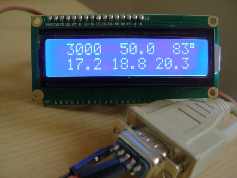
The contrast is better than the above shows. The figures are from a
simple program simulating the Megasquirt output. They represent RPM
(to nearest 100), MAP, CLT temp. The second line is min, average and
max AFR over 32 samples. The display is pretty configurable as
outlined below.
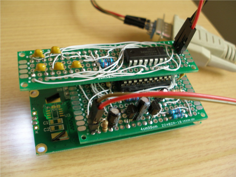
I have socketed the main MSP430 board directly behind pins from the
LCD and, in turn, socketed the RS-232 transceiver board off the back
of that. I could have fitted everything on one larger board but that
would have increased width or height. I'm happier to sacrifice depth.
Besides, the trasceiver board is quite useful for other projects.
I would like to see how small this could be made with a purpose built
board and, perhaps, surface mounting.
After a bit of effort I have a prototype running in one of my cars.
There are a few things yet to be ironed out, but it has promise.
I'll describe the hardware and software and follow with a few
closing remarks.
Hardware
Like all my recent projects I'm using the TI MSP430G2553 20 pin DIP
microcontroller running at 3.6V (its maximum).
The LCD1602 is specified to run at 5V, which is out of spec. for an
input pin of the MSP430. Fortunately, the LCD runs fine at 3.8V which
is acceptable. At this voltage, 0V on the LCD's contrast pin gives a
good contrast. Running the voltage any lower would require the
contrast pin to be brought below ground.
Just as an aside on this, if you look at the divider feeding the LCD
it should deliver 3.9V. The load from the LCD pulls it down the extra
0.1V. I don't suppose this appeals to the purists, but the LCD seems
to be a pretty steady load and I think there's already enough power
going to waste in the divider. Sensible people would probably have
a trimmer here and on the contrast pin to allow for variations between
LCDs.
I stupidly compounded the 5V problem by using a MAX232 transceiver
rather than a 3.3V MAX3232. All part of the learning process. It
only cost an extra divider to bring the Rx pin into the
acceptable range.
Here is the schematic:
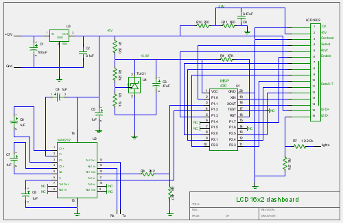
PDF
I haven't implemented the "lights" connection in my prototype. The
idea was to provide dimming of the backlight at night. Truth is that
the white on blue is not terribly distracting at night. Only problem
I've had is with reflections of it in the passenger window and that's
more to do with where I've mounted the LCD. It wouldn't be a problem
if it were recessed back with the main dashboard. That would also
solve some problems with readability in bright sunshine.
I'm still not clever enough to lay this sort of thing out on a PCB and
come up with a feasible one or two layer design. I wired it direct
using AWG30 insulated wire wrap wire soldered on inexpensive (but
decent quality) experimenter's breadboard also off eBay. A tedious
business, but it works.
On top of the electronics there is the question of mounting. On
this I'm at a complete loss as to getting a good looking result. I
made a small steel box and got the circuit board mounted to it with
standoffs. With a bit of fiddling I got the LCD screwed onto the
front of the box and connected to a socket in the circuit board at the
same time. Needed to be pretty accurate with the hole drilling, etc.
I can probably put the box somewhere out of the way, but where or how
do you get something to cover the screws where the LCD mounts to the
box. A job for a 3D printer perhaps?
Truth in advertising -- having already bought 25 MSP430G2553s for a
bit under $2 each, and adding in eBay pricing for everything else,
the parts list would come in at around $8. $2 for the labour
component might be a bit on the cheap side.
Software
I'm a bit more competent in the realm of software and am pretty happy
with the result. I wanted things to be reasonably flexible, so I
included a "master" mode to allow it to talk to a laptop through a
null modem cable for easy reconfiguration. Basically, if it gets back
a "MASTER MASTER MASTER" response rather than a "MS2Extra ...."
response from the "Q" (identify) command, it knows it's talking to the
config software. The dash asks the peer program for a map of which
flash is to be updated. It erases the affected segments, downloads
the new contents (with checksums) and burns them to the erased flash.
The configuration is all contained in the TI's info flash
segments, and that's what will usually be updated. But the above
mechanism also allows the bulk of the firmware to be updated without
needing to pull the chip from the board.
I have used a Perl script to generate the (S19 format) configuration
file from a relatively friendly environment. A real enthusiast might
set up a GUI over the .INI file to make the process a bit less nerdy.
Global Configuration
| Name | Typical value | Meaning
|
|---|
| query_id | Q | String to query ECU identifier
|
| expect_id | MS2Extra Serial330b\0 | Expected response to query_id
|
| query_vals | r\x00\x07\x00\x06\x00\x18 | Command to issue to
retrieve the necessary part of the Megasquirt "OutputChannels". You
can use "A" if you want (though the MSP430 is tight on RAM, but why
download so much more than you need.
|
| pollcycle | 32 | How many samples to gather between display
updates. Must be a power of 2. Polling is always at 16 samples per
second; 32 will have the display update every two seconds.
|
| txdelay | 100 | Pause this x 8�s (in this case 0.8ms)
between chars sent to MS so as not to overrun its input buffer.
|
| resp_len | 24 | How many bytes to expect back when
query_vals has been sent.
|
| background | | 32 characters to replace spaces in the
display after the numbers have been formatted, e.g. to place a fixed
degree symbol after a temperature.
|
| format | | The rest of the config information describes how
to collect and display the values polled from the Megasquirt. Details
below.
|
Per-Value Configuration
The first thing the dashboard needs to know is how to extract the
desired values from the response to query_vals. For this, it
needs to be told an offset in the buffer, and a data
type (supported types are U8, S8, U16 and S16).
To determine these values, refer to the OutputChannels section in the
Megasquirt .INI file.
Here's a section from the .INI file I am using:
rpm = scalar, U16, 6, "RPM", 1.000, 0.0
advance = scalar, S16, 8, "deg", 0.100, 0.0
squirt = scalar, U08, 10, "bit", 1.000, 0.0
firing1 = bits, U08, 10, [0:0]
firing2 = bits, U08, 10, [1:1]
sched1 = bits, U08, 10, [2:2]
inj1 = bits, U08, 10, [3:3]
sched2 = bits, U08, 10, [4:4]
inj2 = bits, U08, 10, [5:5]
engine = scalar, U08, 11, "bit", 1.000, 0.0
ready = bits, U08, 11, [0:0]
crank = bits, U08, 11, [1:1]
startw = bits, U08, 11, [2:2]
warmup = bits, U08, 11, [3:3]
tpsaccaen = bits, U08, 11, [4:4]
tpsaccden = bits, U08, 11, [5:5]
mapaccaen = bits, U08, 11, [6:6]
mapaccden = bits, U08, 11, [7:7]
afrtgt1 = scalar, U08, 12, "AFR", 0.1, 0.0
afrtgt2 = scalar, U08, 13, "AFR", 0.1, 0.0
wbo2_en1 = scalar, U08, 14, "", 1.000, 0.0
wbo2_en2 = scalar, U08, 15, "", 1.000, 0.0
barometer = scalar, S16, 16, "kPa", 0.100, 0.0
map = scalar, S16, 18, "kPa", 0.100, 0.0
#if CELSIUS
mat = scalar, S16, 20, "�C", 0.05555, -320.0
coolant = scalar, S16, 22, "�C", 0.05555, -320.0
#else
mat = scalar, S16, 20, "�F", 0.100, 0.0
coolant = scalar, S16, 22, "�F", 0.100, 0.0
#endif
tps = scalar, S16, 24, "%", 0.100, 0.0
; tpsADC = { tps*10.23 }, "ADC" ; Fake for calibrator and file indexing.
throttle = { tps }, "%"
batteryVoltage = scalar, S16, 26, "v", 0.100, 0.0
afr1 = scalar, S16, 28, "AFR", 0.100, 0.0
In the example global configuration above, query_vals is asking for 24
bytes starting at offset 6 in the OutputChannels. This is the offset
of rpm, and it is an unsigned 16-bit value. At offset 18 comes
map, also an unsigned 16-bit. At offset 22 we get
coolant, a signed 16-bit, and at offset 28 is afr1, also
a signed 16-bit (though it'll never be negative).
By requesting 24 bytes starting at offset 6, all these values will be
retrieved from the Megasquirt. In the buffer that we get back, RPM
will be at offset 0 (6-6), MAP at offset 12 (18-6), etc.
The second thing it needs to know is how to accumulate these
values. The dashboard software currently supports 4 accumulation
methods:
| Method | Action
|
|---|
| mean | accumulates the mean of all samples
|
| min | keeps the smallest value sampled
|
| max | keeps the largest value sampled
|
| last | keeps the last value sampled
|
Finally, after completing pollcycle polls, the dashboard
has to format each accumulated value on the display. For this, in
addition to the signed/unsigned attribute already known, it needs four
numbers: the position of the leftmost digit on the display, the
total field width, the number of digits of precision (to
the right of the decimal point), and a number of digits to
discard from the right.
Display positions on the first line are from 0 to 15; the second line
runs from 16 to 31. Width and precision are reasonably
self-explanatory. Discarding digits is done to eliminate jitter
and/or to save display space.
With a bit of luck, an example will make this clearer:
format => [
	# RPM
	{
		o_buf => 0,
		o_disp => 0,
		o_type => 'U16',
		o_method =>'mean',
		o_discard => 2,
		o_fmt => "3"
	},
	# MAP
	{
		o_buf => 12,
		o_disp => 6,
		o_type => "U16",
		o_method => "mean",
		o_discard => 0,
		o_fmt => "5.1"
	},
	# CLT
	{
		o_buf => 16,
		o_disp => 12,
		o_type => 'S16',
		o_method => 'mean',
		o_discard => 1,
		o_fmt => "3.0"
	},
	# Min AFR
	{
		o_buf => 22,
		o_disp => 18,
		o_type => "U16",
		o_method => "min",
		o_discard => 0,
		o_fmt => "4.1"
	},
	# Max AFR
	{
		o_buf => 22,
		o_disp => 25,
		o_type => "U16",
		o_method => "max",
		o_discard => 0,
		o_fmt => "4.1"
	},
By discarding two digits of RPM and displaying up to three leading
digits, jiggle in the units and tens is eliminated. Combining this
with a strategically positioned "00" in the background spec
allows a meaningful RPM value to be displayed.
Similarly, CLT discards the tenths of a degree, which doesn't hurt
its usefulness to a human.
AFR shows how you can bracket the minimum and maximum values on the
display, the range being potentially more useful than the average.
Closing Remarks
The MSP430 is not working very hard for this. I've opted to run it at
12MHz (which gives a very accurate 115,200 baud rate) but it spends
the vast majority of the time suspended.
The code occupies nearly 2094 bytes (784 fixed, 1310 updatable in
master mode) of the 16k of flash, so there's certainly plenty of spare
room. It's written in assembly language which I find strangely
enjoyable on this chip. Then again, I enjoy it on the M9S12 too;
probably me that's strange.
I haven't catered for a Celsius temperature display. Wouldn't be
hard to add a (say) F16 data type which knows it's receiving
Fahrenheit and wants to turn it into Celsius -- but it seems
inelegant. I don't have much problem reading 185 as 85 and that's
where my temps tend to be.
Fixing the sample rate at 16 per second is possibly controversial.
Given that it's not retrieving much per poll, it's not adding much
burden to the Megasquirt. If the "A" (all output channels) command
was used instead, that might load things down a bit. Once again, it
wouldn't be hard to add configuration for the polling interval (two
16-bit numbers would give full flexibility).
Various things I've made configurable might allow this to talk to
other pollable RS-232 devices, but then I've spoiled it by not giving
a configuration parameter for baud rate (another two 16-bit values,
etc.).
One quite appealing thought occurred to me. There are a few unused pins
and it wouldn't be hard to map things around a bit to have an SPI.
Hook it up to an SD card and, besides the live dashboard, you would
have a log file to examine afterwards. I looked into it for a couple
of hours. Turns out these SD cards are (just like everything else)
much more complicated than you might think. The upshot was that I
could probably manage dumping raw records to the card, but no FAT file
system or anything else (the 512 byte FAT buffer is just neatly 100%
of this processor's RAM!). In the end I decided that it's better to
get something completed than to embark on something probably too
ambitious.
A similar thought about transmitting the values wirelessly also
occurred to me but I don't have any wireless gadgets except the
laptop, so why bother? Besides, while I haven't looked into it, I
expect a wireless protocol would be at least as demanding to implement
as FAT.
Another rather easier idea would be to make use of the 8 user-defined
characters these displays support. The third page of info flash would
just be enough to define 8 chars. This might allow some sort of
hieroglyphic to mean kPa or RPM. Alternatively they might be used for
some sort of bar graph. Neither is terribly appealing. In the first
case, you're not going to end up with anything readable; in the
second, the slow refresh would kill it and it'd be better to use a
graphical LCD (for under $20 on eBay) if you want graphics.
There is a significant race condition when the Megasquirt and
dashboard start up. Because one of the very first things the MS does
is to look at its serial Rx pin and, if it's at logic false, enter
monitor mode. Having the dashboard coming on at the same moment as
the Megasquirt means that if the dash gets its MAX232 fired up before
the MS looks at this pin, things work; if the dash is too late, the MS
sits there at a monitor prompt, not priming the pump or doing any of
its proper duties. Two kludges come to mind: put a delay capacitor on
the power relay for the Megasquirt so that it always comes up after
the (non-relay wired) dashboard; or change the code in the dashboard
to recognise the monitor prompt and, if it sees it, issue an
appropriate monitor command to reboot the Megasquirt. Both ideas are
pretty icky.
Update:I have implemented the Megasquirt reset kludge. It was
simple to do and it's much better having the fuel pump prime first
time.
After all the palaver making sure the LCD's voltage was within spec
for the MSP430, I didn't end up doing any reading from it. Rather
than read its busy/ready pin (Data7), I just stuck to the datasheet's
timing specs. So the LCD's R/W pin doesn't really need to be
connected to the CPU. OTOH, the software would probably be neater and
be able to deal with a larger number of LCDs if it used the handshake.
Necessity is the mother of invention. The slow refresh of the LCD
kind of forced me to come up with the min/max methods. As it turns
out, they're quite an improvement on a simple average. If the
readings are stable, they'll not be much different from the average,
but they let you know when things become spiky.
Source Code
If you'd like a copy of the source or the schematic file (for
gEDA's gschem), or you have some comments, drop me an e-mail at
robsproj9@gmail.com or PM me as robs at the
MS2/Extra forums.